Why
Throughout the Fall 2014 and Spring 2015 semesters, a handful of mechanical engineering students and I at the University of Nevada Reno came together to design and manufacture an electrically operated valve actuator system. Working in conjunction with ElectraTherm, a small renewable energy company of Reno, the primary goal of the project was to design an electrical replacement for ElectraTherm's pneumatically operated safety valves used in their Green Machine, a product which produces power from waste heat. In addition to electric operation, ElectraTherm also required that the valves maintain a less than one second closing time, while remaining capable of returning to the normal valve position should the Green Machine experience a loss of power. Additionally, a supplementary goal to actuate the valve from a normal position within 5 seconds was also requested.


Driving System
Inspired by the Geneva Mechanism, used to actuate the second hand in some older clocks, we decided to employ a cam system to transfer energy from the electric motor to the rack and pinion system. The advantage of this system is that it allowed us to control the angle of rotation, ensuring 90 degrees of actuation from the resting position. In addition to controlling the angle of rotation, the cam system also allows the driving gear (the lighter-in-color aluminum part) to continue to rotate past 90 degrees so that the driven gear (the darker colored steel part) may return to the normal position at system shutdown. This can be seen in the above video, as the driving gear will rotate a full 360 degrees, while the driven gear will oscillate between 0 and 90 degrees of rotation.
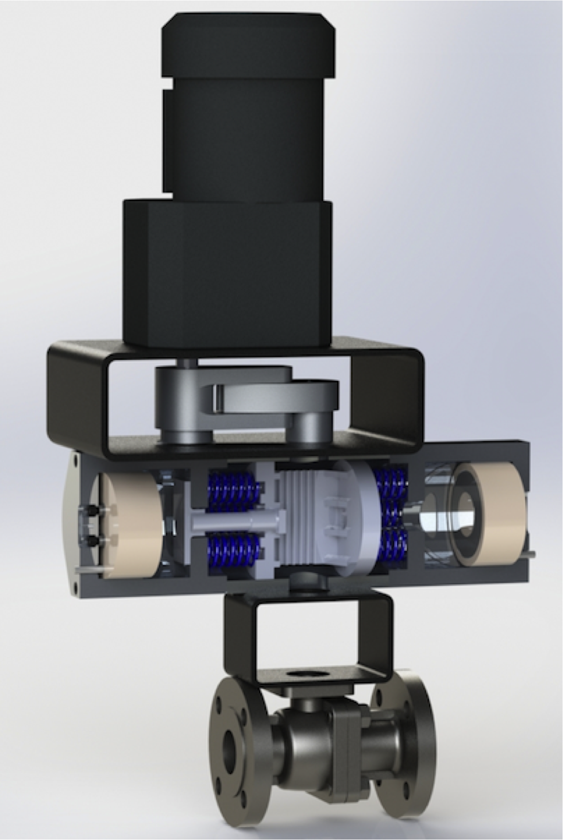
Spring / Electromagnet Housing


The assembled housing contains the second and third actuation systems to assist in both maintaining the actuated position, and to return the actuator to the normal state. These phases of actuation are achieved with both the original spring return system from the original pneumatically actuated system, as well as a new electromagnetic catch system which maintains valve position after the initial phase of actuation.
Additionally, The decision to retrofit the existing pneumatic actuator was critical to success of our project, as the freedom to avoid designing the entire system from scratch significantly impacted the design phase. The benefits from this decision ranged from saving a week in manufacturing parts, to actually kick-starting our design process. It was not until the first week of the spring semester when the majority of our classmates had long since decided on a deign that the decision to produce a retrofit came to us, and the result propelled us further than all but a few of our classmates. By the second week of school, we had finalized the design of the housing and begun coordinating with a machine shop in California to begin producing parts.
Electromagnet Catch
Perhaps the most fulfilling part of the design, while also being the most frustrating part of the manufacturing / testing phase was the electromagnet catch system. The idea behind the system was to capture and restrain the rack at the greatest extent of actuation with an electromagnet. To achieve this, we would have to modify the rack to be able to hold a low alloy striker plate, so that the rack could interact with the magnet. In our eyes, the genius of the system was it's ability to fulfill the safety requirement that the actuator be capable of returning to a normal position under a loss of power.
Unfortunately, what we failed to recognize during the design phase, and found almost immediately during the build phase, was how precisely the throw distance of the rack would have to be monitored. To successfully capture the racks, the striker plates would have to make contact with both magnets at almost the same time. Additionally the striker plate and magnet must be parallel, otherwise only a fraction of the magnetic field would engage the striker plate. The result of taking for granted the striker plate throw distance was several weeks of missed classes and work, late or incomplete homework, and a brief but intense moment of fear from a crashing system while looking for the sweet spot.


During the first weekend of testing we had a pretty good idea that position of the striker plates was off, but we hadn't stopped to consider the effects of adjusting the system without measuring our adjustments. After watching the motor fully actuate the cam system, hearing one or both of the striker plates engage the magnets followed by a swift return to the resting position, one of my teammates in frustration decided to almost fully extend both striker plates, thinking that perhaps only one of the magnets was engaging. The adjustment resulted in the cam system partially actuating while the rack, striker plate and electromagnet bound restricting further rotation. The motor then continued to rotate, tearing the driven gear off the pinion and shearing the square key connecting the motor and driving gear.
Afterwards we found that the tower we were driving on top of the pinion gear was actually a second piece, held to the pinion by a socket hex screw. This also allowed us to create a new pinion tower, which fully contacted the star shaped recess within the pinion gear, providing for additional strength during the actuation of the driven gear.
Conception to Completion
Ultimately my capstone team and I were able to bring our concept to life while meeting the requirements set forth by ElectraTherm. Albeit bigger than we had hoped, the actuator operates entirely on electrical power, bringing the valve to the active position in under 5 seconds, while also capable of returning to the normal position within 1 second. The actuator also fulfills the safety requirement of returning to a normal position under a loss of power through the use of an electromagnet catch system.
Though as a retrofit the actuator is not without it's faults requiring careful calibration of the electromagnet and striker plate catch mechanism. As such, If this system were to go into production, it is recommended that some sort of external calibration mechanism be incorporated to alleviate this situation. However in light of this oversight, it should be noted that the device was capable of meeting all customer design specifications.